
Rosalee Wolfe
DePaul University
wolfe@cs.depaul.edu
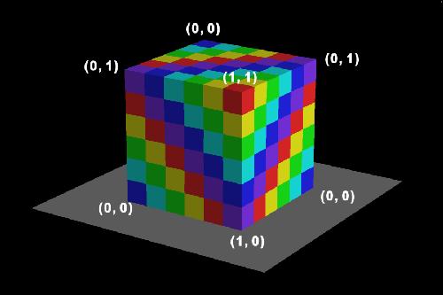
| 30: This technique can be applied to objects that aren’t parametrically defined by assigning u,v values to each vertex. As long as the chosen values range between zero and one, it’s possible to use the same texture mapping approach. | |
| 31: By using a nonlinear function, it’s possible to pull or distort the texture maps over the surface of polygons. | |
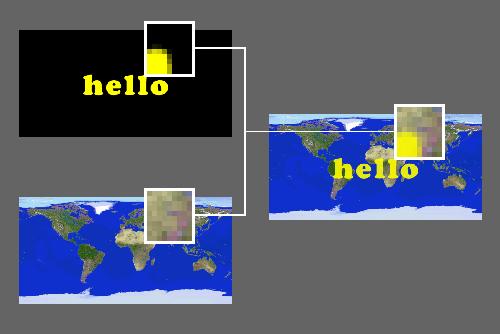
| 32: We can layer textures one on top of another by using a technique similar to the one that allows television viewers to see a forecaster standing in front of a weather map when in actuality the forecaster is standing in front of a blue wall in a studio. The colors of the background weather map is substituted for the blue color. (Have you noticed that they never wear blue?) We can do the same thing. We want to place the word "hello" on top of a map of the world. The black background of the "hello" image will be treated as transparent. To create a pixel in the final image, we find the colors in the corresponding pixel locations in the two input images and combine the two. | |
| 33: Here is an example of layered textures. :-) | |
| 34. Bo Peep is a character from "Toy Story". "Toy Story" made history as the first computer animated feature film and was created by Disney and Pixar. What texture techniques are at work in this image? What was the map shape for the wall? For the lamp? | No Image |
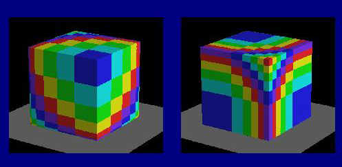
| 35: A major drawback to 2D texture mapping is the necessity of handling singularities. For instance, a spherical mapping has two singularities, one each at the North and South Poles. Just as it makes no sense to talk about the time zone at the North Pole, it’s impossible to determine the second texture coordinate by the usual mathematical conversion. A programmer has to anticipate singularities and handle them as special cases or the program will bomb. | |
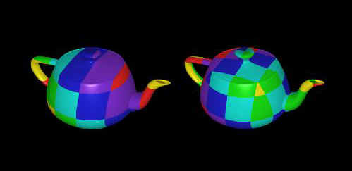
| 36: In a 2D planar mapping, a checker pattern degenerates into stripes along the axis being projected, which does not happen with a 3D mapping of a checker pattern. | |
![]()
![]() Main Mapping Page
Main Mapping Page
![]() HyperGraph Home page.
HyperGraph Home page.
Last changed May 29, 1999, G. Scott Owen, owen@siggraph.org